- 您现在的位置:买卖IC网 > Sheet目录1250 > TSSOP20EV (Microchip Technology)BOARD EVAL FOR MCP43X
�� �
�
�Programmable� Gain� Using� Digital� Potentiometers�
�V� OUT� =� –� R� BW� x� V� IN�
�Programmable Ampli?er Gain Using a�
�Digital� Potentiometer�
�Many� sensors� require� their� signal� to� be� ampli?ed� before�
�being� converted� to� a� digital� representation.� This� signal� gain�
�may� be� done� with� and� operational� ampli?er.� Since� all� sensors�
�will� have� some� variation� in� their� operational� characteristics,�
�it� may� be� desireable� to� calibrate� the� gain� of� the� operational�
�ampli?er� to� ensure� an� optimal� output� voltage� range.�
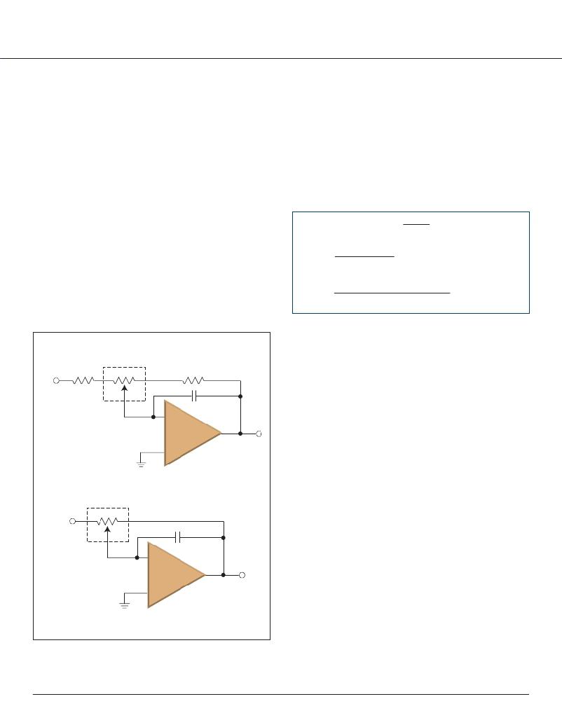
�The� ?gure� below� shows� two� inverting� ampli?er� with�
�programmable� gain� circuits.� The� generic� circuit� (a)� where� R� 1� ,�
�R� 2� ,� and� Pot� 1� can� be� used� to� tune� the� gain� of� the� inverting�
�ampli?er,� and� the� simpli?ed� circuit� (b)� which� removes�
�resistors� R� 1� and� R� 2� and� just� uses� the� digital� potentiometers�
�R� AW� and� R� BW� ratio� to� control� the� gain.�
�The� simpli?ed� circuit� reduces� the� cost� and� board� area� but�
�there� are� trade-offs� (for� the� same� resistance� and� resolution),�
�Equation� 1-1� shows� how� to� calcultate� the� gain� for� the�
�simpli?ed� circuit� (Figure� 1-1b).� The� gain� is� the� ratio� of� the�
�digital� potentiometers� wiper� position� on� the� R� AB� resistor�
�ladder.� As� the� wiper� moves� away� from� the� midscale� value,�
�the� gain� will� either� become� greater� then� one� (as� wiper� moves�
�towards� Terminal� A),� or� less� then� one� (as� wiper� moves�
�towards� Terminal� B).�
�The� device’s� wiper� resistance� (R� W� )� is� ignored� for� ?rst� order�
�calculations.� This� is� due� to� it� being� in� series� with� the� op� amp�
�input� resistance� and� the� op� amp� input� impedence� is� very�
�large.�
�Circuit� Gain� Equation�
�R� AW�
�Using� the� R� 1� and� R� 2� resistors� allows� the� range� of� the� gain�
�to� be� limited� and� therefore� each� digital� potentiometer� step�
�is� a� ?ne� adjust� within� that� range.� While� in� the� simpli?ed�
�R� BW� =�
�R� AB�
�#� of� Resistors�
�x� Wiper� Code�
�circuit,� the� range� is� not� limited� and� therefore� each� digital�
�potentiometer� step� causes� a� larger� variation� in� the� gain.�
�The� feedback� capacitor� (C� F� )� is� used� for� circuit� stability.�
�Inverting� Amplifier� with� Programmable� Gain� Circuits�
�Generic� Circuit� (a)�
�Pot� 1�
�R� AW� =� # of Resistors� –� Wiper Code� x� R� AB�
�#� of� Resistors�
�V� IN�
�R� 1�
�A�
�B�
�R� 2�
�W�
�C� F�
�Op� Amp� (1)�
�V� OUT�
�Simplified� Circuit� (b)�
�Pot� 1�
�V� IN�
�A�
�W�
�B�
�C� F�
�Op� Amp� (1)�
�V� OUT�
�Note� 1:� A� general� purpose� op� amp,� such� as� the� MCP6001.�
�Signal� Chain� Design� Guide�
�13�
�发布紧急采购,3分钟左右您将得到回复。
相关PDF资料
TSV250-130F-2
POLYSWITCH PTC RESET 0.13A SMD
TSV250-130F-B-0.5-2
POLYSWITCH PTC RESET 0.13A SMD
TURBO-DECO-XM-UT3
SITE LICENSE TURBO DECODER XP
TVB058SA-L
SURGE PROTECTOR 58V DO-214AA
TVB200SA-L
SURGE PROTECTOR 200V BREAKOVER
TVB200SC-L
SURGE PROTECTOR 200V BREAKOVER
TVB270SB-L
SURGE PROTECTOR 270V DO-214AA
TVB270SC-L
SURGE PROTECTOR 270V DO-214AA
相关代理商/技术参数
TSSOP-28
制造商:UTC-IC 制造商全称:UTC-IC 功能描述:16-BIT CCD/CIS ANALOG SIGNAL PROCESSOR
TSSOP-56
制造商:FAIRCHILD 制造商全称:Fairchild Semiconductor 功能描述:Fairchild Semiconductor Product Package Material Disclosure
TSSOP-8
制造商:AOSMD 制造商全称:Alpha & Omega Semiconductors 功能描述:Tape and Reel Dimensions
TSSOP-8PIN
制造商:IRF 制造商全称:International Rectifier 功能描述:Package Dimensions
TSSOP-B14J
制造商:ROHM 制造商全称:Rohm 功能描述:IC Packages
TSSOP-B8
制造商:ROHM 制造商全称:Rohm 功能描述:LSI Assembly
TSSOP-B8J
制造商:ROHM 制造商全称:Rohm 功能描述:LSI Assembly
TSSOP-C10J
制造商:ROHM 制造商全称:Rohm 功能描述:LSI Assembly